This article describes a clever and simple automatic battery charger circuit that only uses two transistors! This circuit automatically adjusts the charging power based on the battery's charge level, by turning the charger on and off.
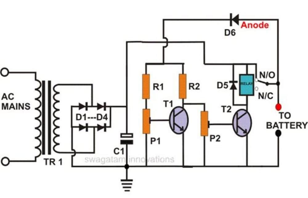
Circuit Working
The magic behind this circuit lies in the two transistors. They work together to sense when the battery is full and automatically shut off the charger. This design is actually more sensitive than using just one transistor.
How it Charges and Stops
One transistor (T1) is set to turn on only when the battery reaches its full charge level. When this happens, the other transistor (T2) shuts off, which cuts power to the relay. The relay then disconnects the charger from the battery.
Discharging brings the battery voltage back down. As this happens T1 can no longer turn on because the voltage isn't high enough.
This triggers T2 to turn on, which activates the relay and reconnects the charger to the battery resuming the charging process. This cycle keeps repeating, ensuring the battery is charged but not overcharged.
How to Setup the Circuit
Here's how to set up this automatic battery maintainer charger circuit:
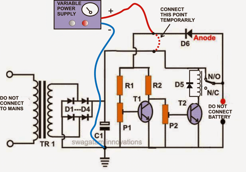
- Start with a Safe Power Source: Don't connect your fixed transformer yet. Instead use a separate power supply that can be adjusted from 0 to 24 volts.
- Temporary D6 Connection: Disconnect the positive lead of diode D6 from the relay contact, and connect it to the positive terminal of your adjustable power supply.
- Preset Centered: Set both presets (P1 and P2) to the middle of their range.
- Power Up and Adjust Voltage: Turn on the adjustable power supply, and slowly increase the voltage to 11.5 volts or lower.
- Fine-Tune Relay Activation (P2): Adjust preset P2, until the relay just clicks on (activates).
- Fine-Tune Relay Deactivation (P1): Increase the voltage on the adjustable power supply to about 13.5 volts. Now, adjust preset P1 until the relay just clicks off (deactivates).
- Calibration Complete! You've calibrated the circuit. Double-check by slowly raising and lowering the voltage to ensure the relay functions as expected.
- Connect Your Fixed Power Supply: Now remove the adjustable power supply and connect your fixed transformer with bridge rectifier circuit.
- Important Reminder! Remember to reconnect the positive lead of diode D6 back to the relay contact (or the positive terminal of the battery you'll be charging).
How it Works Now:
With this setup the battery will only charge, when its voltage falls below a certain level (the "window"). Once the battery reaches a higher voltage, (also within the window), the relay will automatically shut off charging to prevent overcharging.
Parts List
- R1, R2 = 10K = 2
- P1, P2 = 10K PRESET = 2
- T1, T2 = BC 547B = 2
- C1 = 2200uF/25V = 1
- C2 = 47uF/25V (Please connect this capacitor across the relay coil) = 1
- D1---D4 = 1N5408 = 4
- D5, D6 = 1N4007 = 2
- RELAY = 12 VOLT, SPDT = 1
- TRANSFORMER = 1, (AS PER THE CONNECTED BATTERY AH (DIVIDE BY 5)

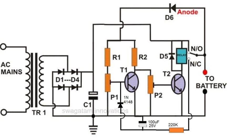
This diagram illustrates the steps involved in calibrating the circuit's automatic shut-off levels using a variable power supply.

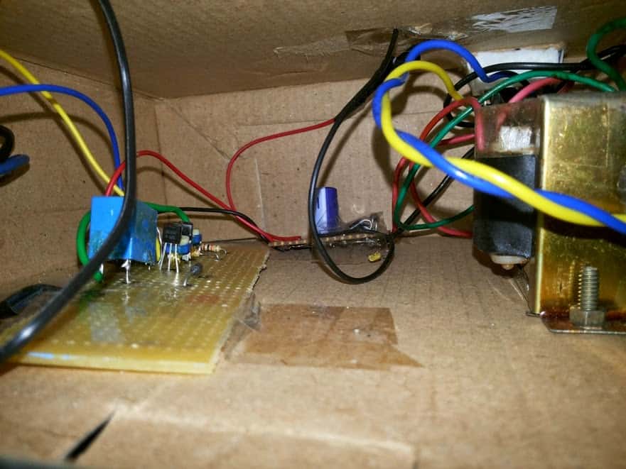
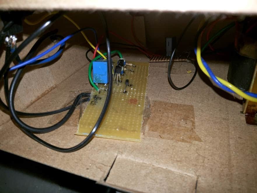
Circuit Built and Tested by a Passionate Hobbyist!
This self-regulating battery charger, maintainer circuit was successfully built and tested by an electronics enthusiast. The following images showcase their talent and dedication to the field.
For Automatic Shut-Off and Hold:
If you like this circuit to automatically shut off charging upon reaching full battery level and stay off until the battery voltage drops again, here's a modified design you can consider.

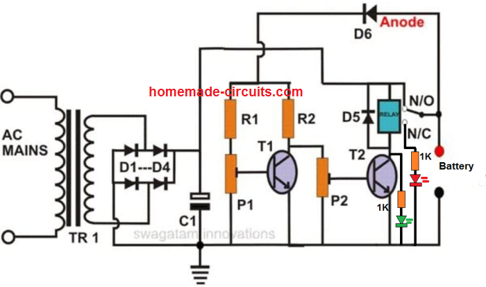
Important Tips:
- Prevent Relay Latching: To avoid the relay immediately turning on, when you switch on the power, always connect the discharged battery first across the designated terminals. Then, turn on the power supply.
- Adding Charging Status LEDs (Optional): Want to see if your battery is charging? You can easily add a couple of LEDs to the circuit, as shown below. This will provide a visual indication of the charging status.