
This tutorial demonstrates how to build a circuit that, like a moving bar graph, illuminates LEDs one at a time.
Using a certain chip (IC 4017) that might not be the best choice for this project is discussed in the original article. We'll look at how we might modify it to suit our needs.
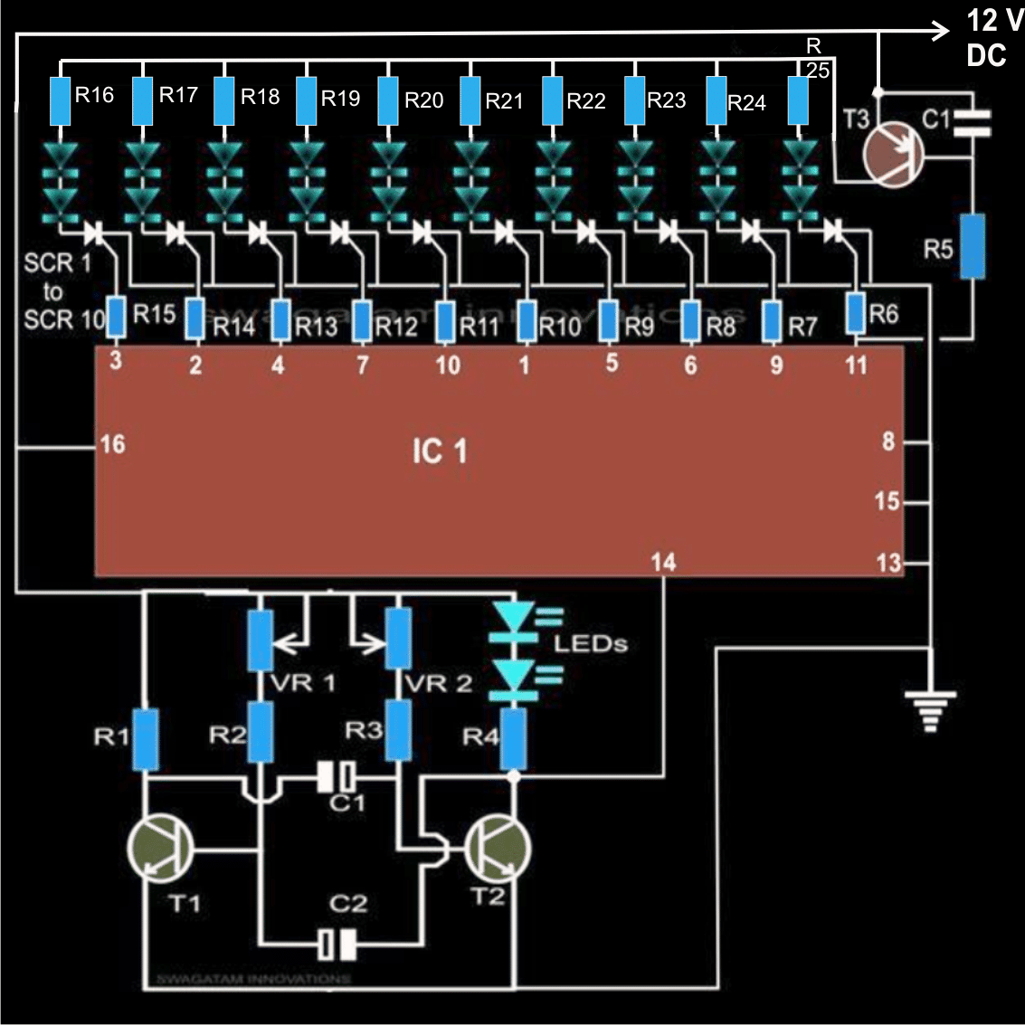
Consider that every LED is linked to a different output pin on the chip. The LEDs light up sequentially as a result of the chip turning on each of these pins individually during circuit operation.
This design creates a nice lighting effect with a simple chip. You may play around with various LED configurations and control elements.
How the Circuit Works
The ubiquitous 4017 chip, also referred to as a Johnson's Decade Counter, is the foundation of this LED sequencer circuit.
Normally, the outputs of this chip are used to count from 0 to 9 (the decade). A clock pulse applied to pin 14 causes it to turn on each output individually.
The "high" signal on the outputs provides the effect of a spotlight traveling across a stage.
However, we won't obtain the desired bar graph effect if we attach LEDs to these outputs. Instead, one LED would turn on at a time, bouncing like a single illuminated "dot" racing across the LEDs from one output to the next.
Circuit Diagram

The circuit produces a nice impression of sequential illumination, albeit it may not be as striking as you might expect. This is due to the sequence's employment of only one LED at a time, which results in relatively low total light.
The chip's (4017) useful feature, however, is its capacity to autonomously sequence, that is, cycle, through its outputs.
It would be difficult to accomplish this complicated job with a single, less sophisticated processor.
Therefore, the task at hand is to increase the illuminated LEDs' brightness while preserving the cool sequencing effect.
Keeping LEDs Lit is the Challenge
Here, keeping the previously lit LEDs from going out of order as the series goes on is crucial. In this manner, as each LED turned on, a luminous "bar" would form, illuminating the whole array.
The process would reset, turning everything off before beginning again, once all of the LEDs were on.
Sadly, there is no way to change the chip itself. So, outside elements hold the key to the answer.
In order to provide this "hold" feature, an LED-operated latching mechanism must be included. When the sequencing signal drops, this latching circuit will effectively "remember" which LEDs were switched on and maintain their light.
The Fix: Using SCRs to latch
An SCR (Silicon Controlled Rectifier) is a component that can help us resolve the LED hold problem.
The capacity of SCRs to lock their output "on" in response to an applied signal to their gate is well known. Since our circuit currently uses DC power, it is handy that this latching only operates on DC power.
Every output pin of the 4017 chip is linked to the gate of a matching SCR, as can be seen in the diagram.
Next, the anode of each SCR and the LEDs themselves are linked across the positive supply voltage. Because of this arrangement, even when the chip's output drops, the SCRs may latch onto the sequencing signal and keep the LEDs glowing.
The Method of Sequencing
One by one, the SCRs activate as the chip (4017) generates its sequence pulses. This illuminates the bar graph by sequentially turning on the LEDs and latching them in the "on" state as they go on, illuminating the LED at the end. The LED chain as a whole stops after that.
Transistor T3 is in charge of this cutoff feature. Since pin 11 on the chip is low, the PNP transistor continues to conduct (ON). Pin 11, the final output in the sequence, stays low until the end of the sequence. Pin 11 eventually rises to the top as the sequence comes to a finish.
Pin 11's high signal effectively turns off T3 by cutting off its base current. The LEDs and SCRs lose power as a consequence.
By doing this, the entire LED array is turned off and the clasp holding the SCRs on is broken. After everything is reset, the procedure continues and LED 1, which is attached to pin 3 of the chip, lights up.
Controlling the speed
The frequency of the clock pulses delivered to pin 14 of the device determines how quickly the LED bar graph series moves (407).
These clocks may be produced via an astable multivibrator circuit. Because it is straightforward to construct and configure, an astable multivibrator (AMV) based on transistors is employed in this design.
You may alter the frequency of the clock pulses by varying the values of capacitors C1 and C2.
This in turn regulates the apparent motion speed of the LED bar. An approach is to connect resistors R2 and R3 in series with variable resistors (VR1 and VR2).
This enables you to use a knob or dial to directly regulate the display rate.
Making the Circuit Perfect:
The capacitor located at the base of T3 is what somewhat delays its turn-off. This makes sure that before the entire array goes off, the last LED, which is attached to pin 11, has enough time to fully light up.
Resistors for limiting current (R5–R15): these resistors control the amount of current that passes through the chip and SCRs (4017).
This keeps the chip from overheating and stops the SCRs from drawing excessive current.
Power Supply: A DC voltage range of 5 to 15 volts can be used to run the circuit. A 12-volt supply allows you to connect up to four LEDs in series.
But each LED will require the addition of a current-limiting resistor (which is not indicated in the figure but is required).