
This article discusses a few basic circuits for DC over voltage protection crowbars. With the description that follows, let's discover how each crowbar circuit operates.
Definition of Crowbar Circuit
The term "crowbar circuit" has a straightforward meaning, in case you were wondering. This circuit network uses an SCR or transistor to keep an eye on the output voltage.
When the output voltage reaches the chosen limit, the transistor or SCR short circuits the supply wires and blows a series-connected fuse at the input.
When the fuse blows, the input supply is immediately turned off, stopping the output voltage from increasing further and shielding the output load from an overvoltage scenario.
Standard Crowbar Circuit

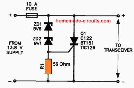
Parts List
- Zener diode 5.6 V 1 watt, 9.1 V 1 watt= 1 each
- Resistor 56 Ω 1/4 watt = 1
- SCR BT151 = 1
- Fuse = 1
This crowbar circuit design, which just uses zener diodes and SCR, is most likely one of the simplest ones. The circuit is simple to comprehend.
The zener diodes fail and provide the SCR gate with the triggering voltage as soon as the voltage across the supply rails begins to rise over a predetermined threshold that is based on the value of the zener diodes.
The fuse blows and cuts off the input supply when the SCR immediately conducts and short circuits the supply rails. The cutoff operation guards against an overvoltage scenario for the output load.
Crowbar Circuit without Fuse

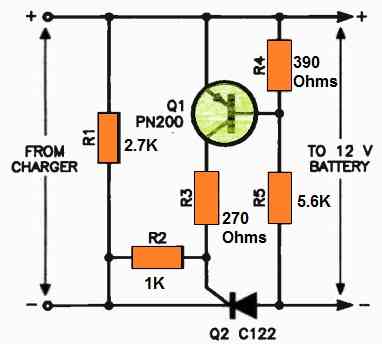
Parts List
- Resistors are 1/4 watt 1% MFR
- 2.7 k, 1 k, 270 Ω, 5.6 k, 390 Ω, = 1 each
- SCR C106 or BT151 = 1
- Transistor PN200 = 1
The circuit above can be helpful to you if you want to design a crowbar circuit without a fuse.
As detailed below, you may use this design in your battery charger to safeguard the battery from an overvoltage scenario.
An easy-to-make crowbar circuit might safeguard a battery charger's rectifier diodes from reverse battery connections and short circuits.
Even with a drained lead-acid battery, there is residual voltage that the circuit utilizes. This voltage is necessary to power the SCR (Q2), the critical component of the circuit.
When the battery is properly connected and the charger is turned on, the rectifier output triggers the SCR every half-cycle when it rises over the battery voltage.
This allows the battery to accept current from the charger.
For the SCR to function, the battery needs to be inserted and the leads shouldn't be reversed or shorted. This stops the current flow and keeps the rectifier diodes safe.
In addition, the circuit features a safeguard against damage to a 6V battery. A 6V battery will not cause the transistor Q1 to turn on, which also keeps the SCR from turning on. This prevents the charger from harming a 6V battery.
Crowbar Over-voltage Protection for 78XX regulators

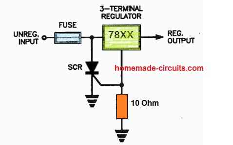
Parts List
As crowbar over-voltage protection, people can utilize the reference terminal bias current of a three-terminal regulator to turn on an SCR crowbar circuit and break a fuse in series with any three-terminal regulator's input.
If the unregulated input voltage rises too high, the reference current will generate an enormous spike in current, activating the SCR and burning the fuse.
Selecting a resistor that can produce adequate bias to turn on the SCR is necessary. Using a sensitive-gate SCR is also essential.
Prototype of Modular Crowbar to Safeguard Power Supply Circuits

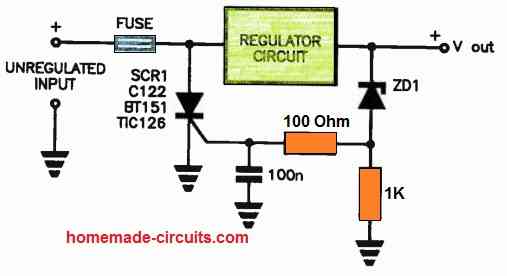
In the event that the series-pass regulator fails, this circuit instantly cuts off the output to safeguard a regulated power supply against excessive voltage.
By doing this, the output is prevented from getting the entire unregulated power, which could harm the connected equipment.
The circuit uses a zener diode, ZD1, to identify an excessive voltage.
One selects the zener diode voltage to be marginally more than the highest voltage that can be output of the supply.
When the voltage across the zener diode exceeds its voltage, the diode operates. Via the zener diode's bias resistor, this current supplies gate current to SCR Q1.
Whenever the SCR operates, the fuse connected in series with the regulator circuit's input melts. By disconnecting the regulator circuit from the power supply, this prevents the unregulated voltage.
The 100nF capacitor that sits between the SCR's gate and ground prevents spikes from turning on the SCR. This guarantees that the SCR will only turn on once the output voltage steadily rises over the voltage of the zener diode.
In a regulated power supply, this circuit provides a simple and dependable way to avoid overvoltage. The cost of building is also not too exorbitant.
Crowbar using Transistor and SCR
The transistor in the following crowbar design is configured for monitoring the input voltage applied from the left. Should the voltage increase above a predetermined threshold, the transistor operates and supplies the necessary current to the SCR, which promptly fires, shorting out the output and safeguarding the load from the danger. Another name for it is a Crowbar circuit.
How it Works
Basic and straightforward, the circuit below illustrates what I mean. The following points can help you understand how the functioning is done:
The right side of the circuit applies the supplied DC input voltage across the SCR.
The SCR stays closed and the transistor cannot continue to conduct for as long as the input voltage is below a specific predefined value.
The voltage across the zener diode essentially sets the level of threshold voltage.
Everything proceeds as planned as long as the input voltage remains below the specified limit.
On the other hand, if the input exceeds the above cutoff point, the zener diode begins to conduct, biasing the transistor's base.
The transistor eventually gets completely biased, which causes the positive voltage to be drawn to the collector terminal.
The SCR's gate is immediately opened by the voltage at the collector.
As soon as possible, the SCR shorts the input to ground and conducts.
Because of the possibility of destruction to the SCR resulting from direct voltage shorting across it, this may appear to be a risky condition.
However, the SCR is still completely safe since the transistor stops conducting and prevents the SCR from reaching dangerously high levels as soon as the input voltage falls below the predetermined threshold.
The circuit may perform the DC overload protection function by maintaining the condition, which maintains the voltage under control and keeps it from rising beyond the limit.

Crowbar equipped with SSB and Triac
The following design, which employs a silicon bilateral switch, or SSB, as the gate driver for the triac, can shield your priceless device from overvoltage scenarios.
By using the preset R2, you may adjust the SSB's triggering point, which is when the device can fire and turn on the triac.
This setting is made in accordance with the required high voltage level, which is necessary for the crowbar to activate and safeguard the linked circuit from potential burnout.
Upon reaching a high voltage condition, the SSB recognizes this over voltage and activates itself in accordance with the R2 preset. It turns on and ignites the triac.
The fuse blows as a result of the triac immediately conducting and shorting circuiting the line voltage. The load receives no electricity soon after the fuse collapses, preventing the risk of an overvoltage.

With low voltage dimmers, a silicon bilateral switch (SBS) is a synchronizable diode.
The SBS breaks when the voltage between the main power terminals, MT1 and MT2, rises over the trigger voltage, which is normally 8.0 V, much lower than the diac. It then keeps conducting as long as the current flowing through it is more than the holding current.
At 200 mA, the holding voltage is around 1.4 V.The SBS will again shut off if the current drops below the holding current.
The component is appropriate for AC operations since it can operate in either direction.The SBS can be conducted by a pulse on gate G even if the trigger voltage is not attained.
Two opposite directions thyristors using one common gate and two zener diodes of roughly 15 V (which begin conducting at 7.5 V) between the anode and cathode nodes and this gate may be used to describe the behavior.
Combining a Zener diode and a triac in a crowbar circuit
In the event that you do not find an SSB, the next illustration illustrates how to create the same crowbar application using a triac and zener diodes.

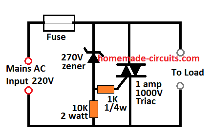
Parts List
- Resistor 1/4 watt 5% 1 k = 1
- Resistor 10 k 2 watt = 1
- Zener diode 270 V 1 watt = 1
- Fuse = 1
In this case, the zener voltage determines the crowbar circuit's shutdown level. The zener begins to conduct immediately as the 270 V threshold is achieved, as seen by the figure. The triac turns on immediately as the zener diode breaks over and begins to conduct.
In order to shut off the fuse and stop any more hazards from the high voltage, the triac turns on and short circuits the line voltage.
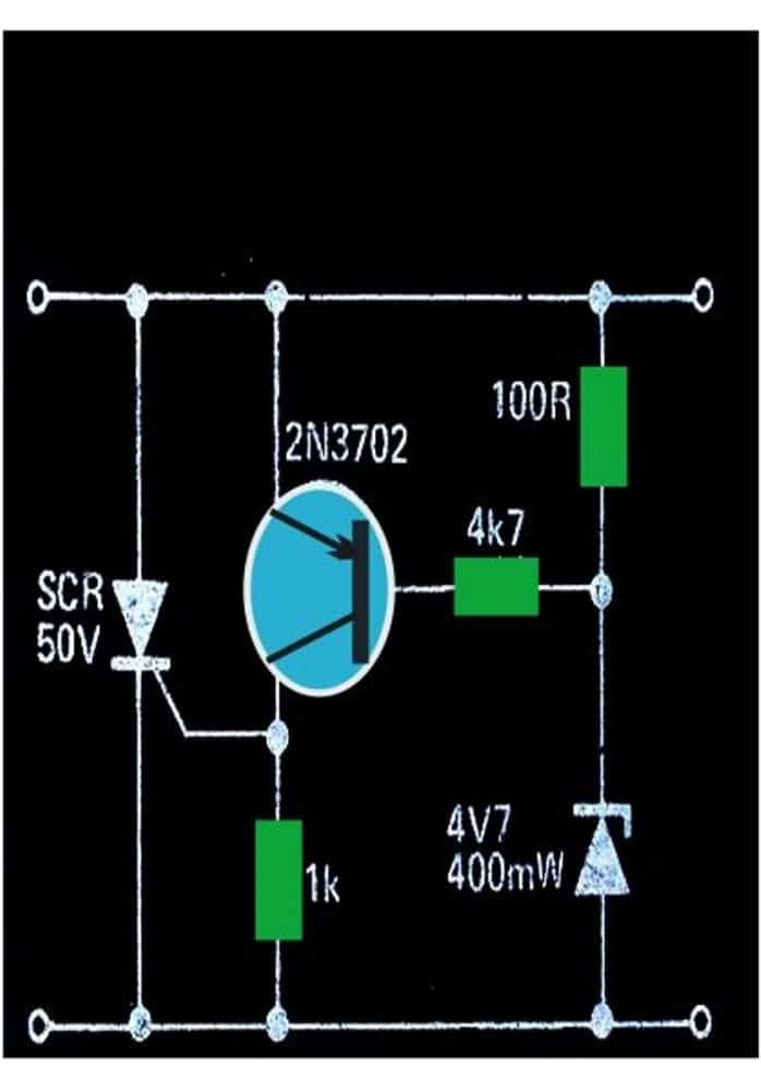
An Additional Basic SCR, Fuse Crowbar Circuit
This is an additional straightforward SCR transistor crowbar circuit that provides protection from over voltage in the event that the voltage regulator malfunctions or there is a high level coming from an outside source.
The intended usage of it is in conjunction with an electrical supply that has a degree of short circuit safety, perhaps a simple fuse or fold-back current limitation.
Since excessive voltage is likely to ruin TTL, a 5V logic supply is an excellent possible solution.
Each of the values of the components used in Fig. 1 relate to a 5V supply, although this crowbar arrangement may safeguard any type of supply up to around 25V with the correct zener diode choice.

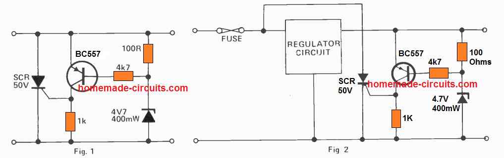
The transistor turns on and initiates the SCR whenever the supply voltage is +0.7V higher than the zener voltage.
This results in a short circuit of the supply, which stops the voltage from rising further.
When using it in a power supply with simply a fuse for safety, it is best to connect the SCR directly onto the unregulated supply, as shown in Fig. 2, to guard from damage to the regulator circuit immediately as the crowbar activates.
Specifications for SCRs
The ideal voltage for the thyristor or SCR has to be greater than the input supply voltage, and the current rating for either device could be around double the expected short circuit current value.
You have two options for reverting the circuit to its initial state: turning off the supply source or using a push button switch between the cathode and anode contacts of the SCR to stop its conduction.