Without the need for a large transformer, this transformerless solid-state automated night light turns on certain LEDs at night and turns them off in daylight hours.
This article explains methods to build an automated darkness-activated LED lamp circuit without the need for a large transformer by utilizing a handful of transistors and a capacitive power source.
Solid-State Transformerless Design
The circuit's primary characteristics are its small size and low current consumption, despite the fact that the idea may appear rather well-known and widespread.
Because there is no transformer included in this circuit due to the capacitive power supply, it is incredibly tiny and may be installed in any little space within the specific building.
LEDs are Most Efficient
The technique is extremely power-efficient and economical since LEDs are used in place of filament bulbs.
Red LEDs are employed in the suggested LED automated day-night light switch circuit design; nevertheless, white LEDs might prove more appropriate for the intended purpose as they would provide superior area illumination.
Using an LDR
It is important to place the LDR such that it does not get any light from the LED and only receives light from the surroundings which is to be detected.
Circuit Working
The following details help clarify the proposed transformerless programmed day/night LED bulb circuit:
The source of the 220 V mains supply is connected to the 10 Ohm resistor while the opposite neutral point.
The initially occurring outburst or voltage influx that could have been detrimental to the circuit's subsequent stages is mitigated by the 10 Ohm resistor.
By placing a MOV or varistor behind the 10 Ohm resistor, you may improve the unit's defense functionality and ground for any possible spikes that could enter after it.
The four diodes that make up the bridge rectifier rectify the voltage to DC while the capacitor lowers the mains electrical current to smaller amounts.
The rectified voltage is filtered by the 1000uF capacitor, and the two transistor regulating circuit receives the filtered DC.
By comparing the voltage difference across the adjustable resistor and conducting whenever the voltage across it reaches maximum levels, the first transistor is configured as a comparator.
When the appropriate amount of light strikes the LDR, the voltage level rises as seen above.
The transistor conducts when the surrounding light level causes the resistance of the LDR to drop lower than the predetermined threshold.
The subsequent transistor is immediately grounded and turned off by the collector of the transistor above.
Additionally, the corresponding LED lights that are linked to the second transistor's collector are turned off right away.
As the light above the LDR drops below the predetermined threshold, most likely around nightfall once the sun sets, the reverse response occurs.
When day breaks and the outside illumination intensity over the LDR hits the predetermined excessive threshold level, the LEDs ignite once again and stay turned on.
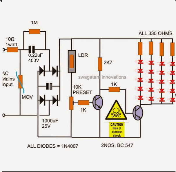
A basic LED automated day and night lamp circuit is depicted in the attached picture.
NOTICE: IF TOUCHED IN POWERED ON CONDITION WITHOUT An APPROPRIATE CONFINEMENT, THE CIRCUIT IS DANGEROUS AS IT IS NOT SEPARATED FROM MAINS AC. It is advised that you handle this circuit with the utmost caution.

Parts List
- Resistors are 1/4 watt, 55 CFR unless specified.
- 10 Ω 1 watt = 1
- 1 MΩ = 1
- 1 kΩ = 2
- 330 Ω = 4
- 2.7 kΩ = 1
- 10 k preset = 1
- LDR any standard = 1
- Capacitors
- PPC 0.22 µF / 400 V = 1
- Electrolytic 1000 µF / 50 V
- 12 V zener diode 1 watt (to be connected parallel to the above 1000 µF capacitor) = 1
- Diode 1N4007 = 4
- LEDs white high bright 20 mA, 5 mm = 20
- Transistors BC547 = 2
- 300 V MOV (optional) = 1
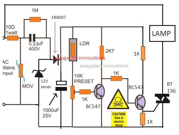
Modifying the Above Design for Activating a 220V Lamp with a Triac

Parts List
- Resistors are 1/4 watt, 55 CFR unless specified.
- 10 Ω 1 watt = 1
- 1 MΩ = 1
- 1 kΩ = 2
- 330 Ω = 4
- 2.7 kΩ = 1
- 10 k preset = 1
- LDR any standard = 1
- Capacitors
- PPC 0.33 µF / 400 V = 1
- Electrolytic 1000 µF / 50 V
- 12 V zener diode 1 watt (to be connected parallel to the above 1000 µF capacitor) = 1
- Diode 1N4007 = 1
- Triac BT136 = 1
- Transistors BC547 = 2
- 300 V MOV (optional) = 1
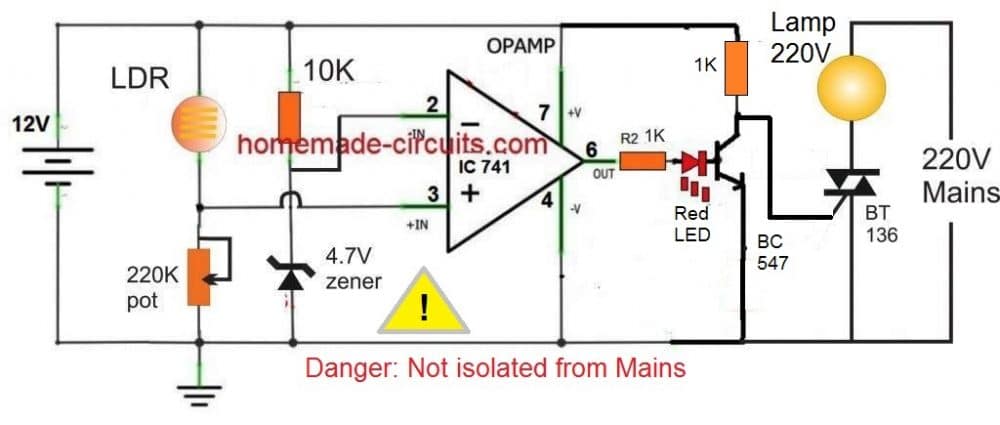
The above triac based design can be further improved by using an opamp controller for achieving a cleaner automatic switching action of the lamp during darkness, as shown below: