
This article explores the workings a couple of highly accurate op amp-based temperature alarm circuits. In essence, a temperature alarm circuit is a device that is intended to sense a level of temperature and emit a warning sound if the temperature rises above or falls below the specified level.
The first temperature alarm circuit described here sounds an alarm anytime the temperature registered by the sensor rises above a predetermined threshold.
The accuracy of the alarm and possible adjustments are covered in more detail below. The LM334Z chip is used by the temperature alarm to sense changes in the ambient temperature.
LM334Z is a Precision Temperature Sensor
The IC LM334Z is a precision temperature sensor device that generates a constant current and alters its output in response to surrounding temperature changes.
When creating temperature gauges, this is useful, but it might be annoying when you're seeking a constant current.
Circuit Description
The following details about the circuit diagram can be used to understand how the op-amp based temperature alarm circuit operates:


A predetermined reference voltage via RV1 is compared to the value created by the current flowing through LM334 across R1. IC2b performs oscillations.
Assume that the voltage of the positive input is greater than that of the negative one. Thus, the op-amp's output is high and somewhat less than Vcc.
Because of R7, R8, and R9, the positive input is now almost two thirds of Vcc. The voltage of the positive input increases as C1 charges via R10, reaching about two thirds of Vcc for as long as the output is high.
The positive input subsequently drops to 1/3 of Vcc due to the op-amp's low output, and C1 begins to discharge.
The process continues when the voltage of the negative input drops to one-third of Vcc, causing the output to become high. Since bizarre oscillator circuits have been the subject of several Tech Tip requests, allow us to provide insight into the reason this circuit oscillates consistently.
The output of the op-amp is ready to go down when the positive and negative input voltages of IC2b are equal. The important thing to note is that C1's voltage continues to rise as the IC's output decreases, ultimately dropping below around two thirds of Vcc.
Regardless of whether the output is dropping, the purpose for the switching action (the greater negative input) is maintained since any reduction in the output voltage instantly drags down the positive input.
The positive input has already fallen substantially below the negative input around the time the output lowers to the point where C1 is no longer able to charge.
This disparity just becomes more with each further output drop, which keeps the switching running until the output hits its lowest point. To be clear, the maximum voltage limit of the LM358 is between Vcc and 1.5V.
Therefore, the idea is still true even when the precise input switching levels aren't precisely 2/3 and 1/3 of Vcc. Regarding the shower alarm, the oscillator operates smoothly once the output of IC2a is low (being cold temperature).
Whenever both the temperature and the output of IC2a are high, D1 and R6 terminate it.
We utilized the recommended transducer primarily because we had one on hand, but you are not restricted to using it.
You are free to explore because we did not precisely match its drive or frequency demands.
You may try changing things up by raising C1 to approximately 10µ, removing LS1 and R11, and connecting a buzzer component to the ground from the output of IC2b.
If you want to configure up the circuit long-term, this modification may function better than the suggested transducer since it changes the alarm to an intermittently buzzing sound.
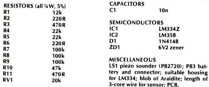
Parts List
The following graphic displays the component list for the op amp based precision temperature alarm circuit described above:

Applications
The temperature-sensitive current source features of the LM334Z semiconductor make it useful in a variety of scenarios.
Because of its linear reaction to variations in temperature, it is very helpful for building thermometers.
Its temperature-dependent output variation may also be used to create temperature alarms, in which frequencies set off alarms depending on variations in temperature.
This dynamic chip provides a precise and flexible framework that allows the development of temperature-sensitive systems.
Precision Temperature Alarm Circuit using Op Amp TL072
The temperature sensor (IC LM335 from National Semiconductors) and a window comparator circuit are used in this following design to create an accurate temperature management solution.


Three different LEDs (red, yellow, and green) are used in this configuration to indicate the status and make tracking the temperature easier.
You may connect a relay driver to activate switching or alarms for further applications. This technique is very helpful for monitoring a heatsink temperature, as demonstrated in applications such as audio power amplifiers.
RV1 and RV2, two trimpots, are used to set the higher and lower temperature ranges. The temperature-dependent reference voltage produced by the sensor, TD1, changes at a rate of 10 mV per degree Celsius.
You may set the green LED to turn on anytime the sensor detects a temperature under about fifty degrees, and the yellow LED to turn on up to about eighty degrees, by altering the predetermined settings.
The red LED is the only one which stays glowing after that. ZD1 operates as a zener diode at 3.3V.
As the dotted lines show, you may optionally add the relay driver to the circuit. It's important to remember that a 12V power source supplies all of the components.