
This post explains how to build an easy transformerless power supply circuits. These circuits are compact and simple and they all use capacitors to step down the AC voltage from the mains without needing any transformers.
Transformerless power supply circuits take high voltage AC from the mains and convert it to lower DC voltage. They achieve this by using a special high voltage capacitor. This capacitor is crucial and needs to have a voltage rating thats higher than the peak voltage of the AC mains to ensure safe operation.
One example of a capacitor commonly found in transformerless power supply circuits is shown below:

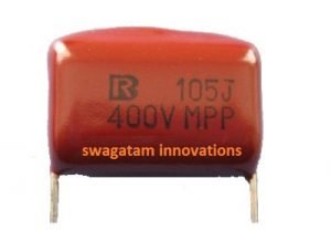
The capacitor connects in series with the AC mains input, preferably on the hot (phase) line.
Its reactance limits the current flowing from the mains. However then the voltage isn't limited by the capacitor.
After rectification you'll measure a high peak voltage (around 310V) which can be alarming.
But there's a solution. A Zener diode at the rectifier output handles this high voltage by regulating it. Just make sure to choose the Zener diodes wattage based on the current allowed by the capacitor.
Warning
- These circuits are NOT isolated from mains power and can be deadly if touched while powered on.
- Extreme caution is required when testing or building them.
- Properly insulate all wiring, especially exposed connections.
- Only build these circuits if you have experience with mains AC safety.
Important Note:
- These circuits are designed for powering small, internal electronics and are not meant for powering external devices.
- Enclose the entire assembly in a well-insulated plastic box for maximum safety.
Understanding the Circuit:
When you turn on the power, capacitor C1 acts like a current controller. It limits the current flowing from the mains based on its reactance (around 50mA in this example). However it doesn't affect the voltage. The full mains voltage (around 220V) reaches the bridge rectifier.
The bridge rectifier then converts this incoming AC voltage (220V) to a higher DC voltage (around 310V). This is because it's converting the AC's RMS value to its peak value. This high voltage might seem alarming, but the Zener diode comes to the rescue next.
The Zener diode acts like a pressure relief valve. Any voltage exceeding its set value (e.g., 12V for a 12V Zener) gets shunted to ground, regulating the output voltage to the desired level (12V in this case).
Finally, capacitor C2 takes the stage. It acts as a filter, smoothing out the remaining ripples in the 12V DC output, providing a cleaner power supply.
Basic Transformerless Design

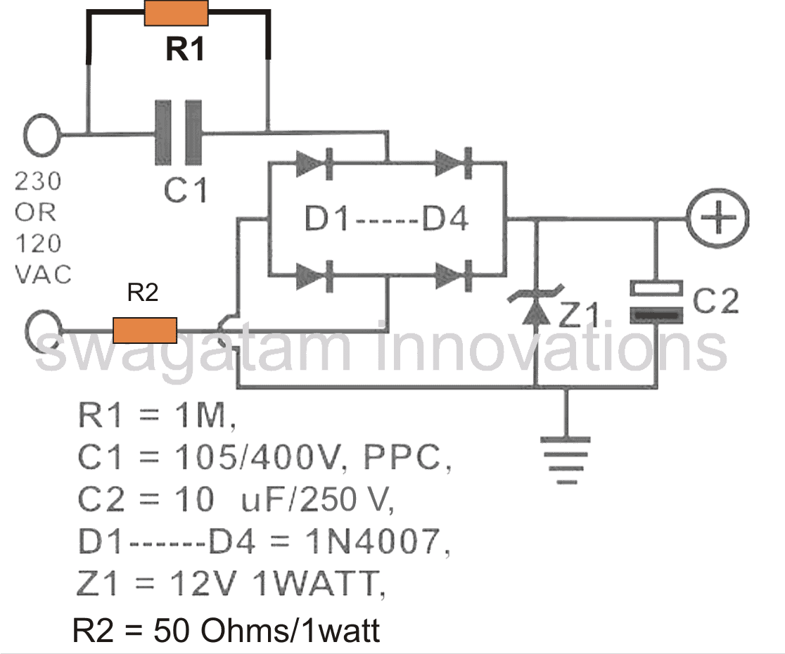
Function of each Component
C1 - The Current Controller:
This capacitor acts as the first line of defense. It limits the high mains current (around 220V or 120V) to a lower level suitable for the output. As a rule of thumb each microfarad in C1 allows roughly 50mA for the load. So, a 2uF capacitor provides 100mA and so on.
R1 - The Safety Discharge Path:
This resistor is crucial for safety. When unplugged, C1 can store the mains voltage, risking a shock if touched. R1 discharges C1 quickly, preventing such mishaps.
D1-D4 - The AC to Low-Current DC Converter:
These diodes form a bridge rectifier. They convert the low-current AC coming from C1 into a pulsating low-current DC. While C1 limits current, it doesnt affect voltage. So, the bridge rectifier's output DC is the peak voltage of the AC (around 310V for 220V AC).
Zener Diode - The Voltage Regulator:
This diode regulates the high voltage (310V) to a desired lower level (like 12V, 5V) by shunting excess voltage, making it suitable for most low-voltage devices.
R2 - Surge Limiter and Current Limiter (Optional):
This resistor might seem redundant with C1 limiting current. However during initial power-on, C1 acts like a short circuit for a moment, allowing high current to flow. R2 prevents this surge from damaging the output by limiting current momentarily. A better option could be an NTC thermistor. NTC offers more precise current limiting.
C2 - The Smoothing Capacitor:
This capacitor filters out the ripples (100Hz) in the rectified DC from the bridge, providing a cleaner and smoother DC output. While a high voltage capacitor is shown, you can use a lower voltage one (like 220uF/50V) due to the Zener diode regulating the voltage.
Advanced Design Considerations
The simple transformerless design has downsides. Resistor R2 is crucial to protect the Zener diode, but it also reduces output current and wastes power due to heat dissipation.
Ideally we want a low R2 value for better efficiency while maintaining safety. Heres how a high-voltage transistor wired in a crowbar configuration can be used to reinforce the Zener diode. (Refer to the following diagram for details.)

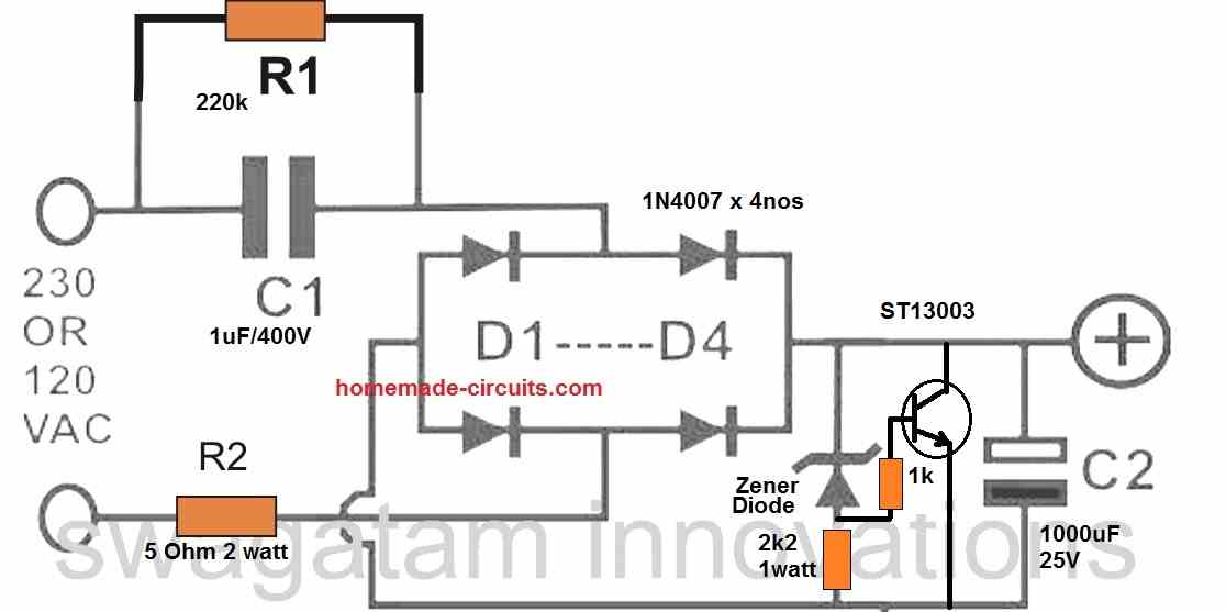
The crowbar design appears fail-proof, offering a very stable output. The transistor acts like a safety switch. If the output voltage from the bridge rectifier tries to exceed the Zener diode level, the transistor conducts, shorting the circuit and grounding the power from capacitor C1. This rapidly drops the voltage.
When the voltage drops below the Zener threshold, the Zener stops conducting, turning off the transistor. This cycle repeats quickly resulting in a stable DC output voltage very close to the Zener diode's voltage.
Alternatively... if you dont want to use the transistor, you can modify the first design as explained below...

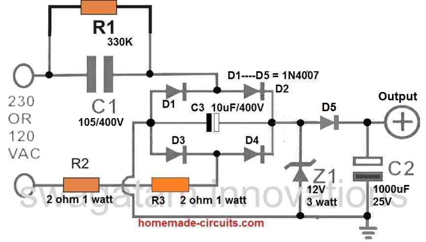
Three improvements were made to the circuit:
- Double Current Limiting: Two resistors (R2 and R3) share the surge current more evenly.
- Surge Absorption: Capacitor C3 grounds and absorbs the initial surge reducing stress on the Zener diode.
- Higher Zener Rating: A 3 watt Zener diode provides increased reliability.
For further improvement replace R2 and R3 with a single 5-ohm NTC thermistor for more precise current limiting.
The design can be further enhanced with additional modifications explained below...

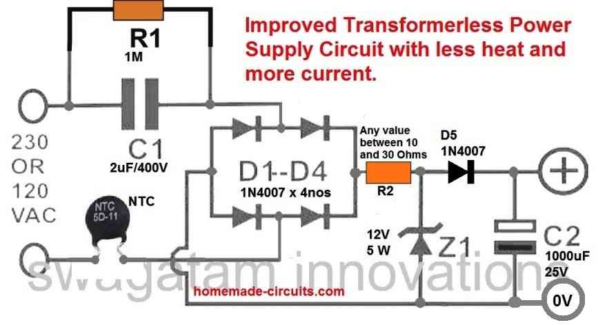
This modification removes the capacitor across the bridge rectifier.
This halves the load on the Zener diode, significantly reducing heat generation.
Additionally, the filter capacitor is now positioned after diode D5.
This placement lowers the capacitor's voltage to a safer 25V. This helps achieving a very high level of filtering, due to its increased value of 1000uF.