Have you ever seen those cool chasing LED lights, at parties? They use bright LEDs to create a flashing, and sequential light pattern. While traditional strobe lights use lasers, this circuit offers a neat alternative using high-power LEDs.
This project will guide you through building a simple yet impressive LED strobe light circuit. The unique aspect of this design is, that it combines a chasing effect with the blinking pulses of a strobe light, creating a more dynamic visual experience.
Let's learn more and see how to make this fun circuit at home!
Circuit Working
This LED strobe light circuit isn't just fun for parties, it's surprisingly versatile! You can use it in toys, decorations, party lights, and even airplane warning signals (think blinking tail lights).
The core of the circuit is a popular chip called the 4017 which normally creates a chasing light effect where LEDs light up one by one. However this circuit kicks things up a notch! We're not satisfied with just chasing lights, but we want them to strobe (flash rapidly) as well.
To achieve this feature we add another chip called the 4049. This chip has multiple functions, and here we use it to create two oscillators. One oscillator controls the flashing (strobing) of the LEDs, and also the other controls the chasing sequence. Both speeds can be adjusted using dials (potentiometers) to create unique and interesting light effects.
The way it works is a bit technical: Normally, the negative terminals (cathodes) of the LEDs would be connected to ground. Instead we connect them to the output of the "buffer" gates in the 4049 chip. These buffers act like a gatekeeper for the ground connection.
When the buffer output is high, it blocks the ground connection, and the LEDs are off. But, when the buffer output goes low, it allows the LEDs to connect to ground and light up. Since the buffer is controlled by the strobing oscillator this creates the rapid on-off flashing effect for the LEDs, even as they chase each other in sequence.
The included diagram shows the complete circuit, where the chasing effect is enhanced with this synchronized flashing effect.
Circuit Diagram

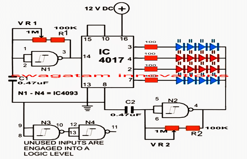
Parts List
- Resistors are 1/4 watt 5% CFR
- 100 k = 2
- 100 Ω = 4
- Potentiometer 1 MΩ = 1
- Capacitor 0.47 µF / 50 V PPC = 2
- LEDs with different colors, 20 mA, 5 mm = 16
- IC 4093 = 1
- IC 4017 = 1
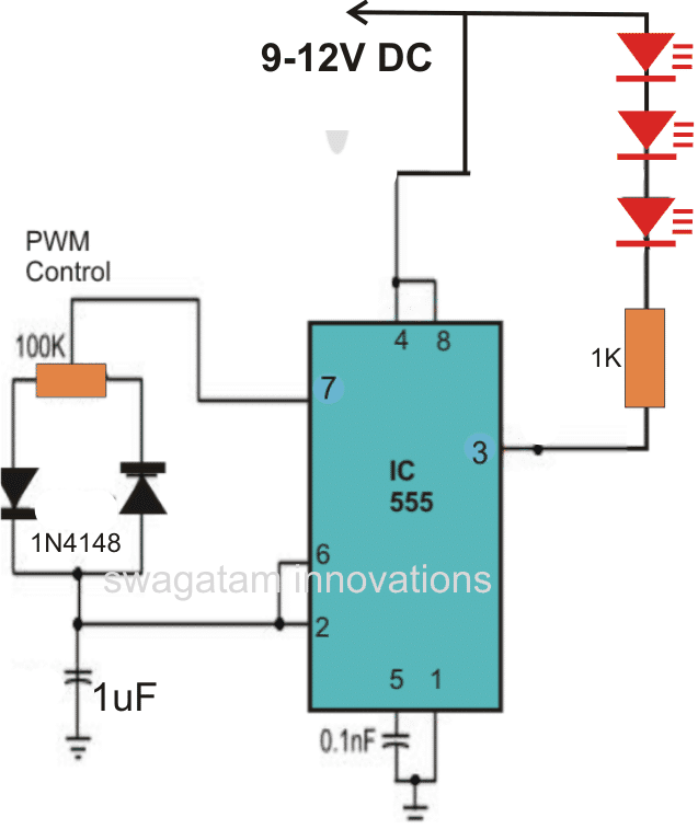
A reader question about a 555 timer strobe light circuit!
One of our readers eager to build the LED strobe light circuit we discussed earlier, ran into a snag while collecting parts. They couldn't find a 1 megohm potentiometer (pot) or a 100 kilohm resistor at the store.
Instead, they:
- Used 4 x 22 kilohm resistors in series to create an 88 kilohm resistor (close enough!)
- Picked up two 100 kilohm potentiometers hoping they might work
With these substitutions, the circuit didn't quite work as expected. Here are the issues they encountered:
- The flash speed adjustment with the 100k pot wasn't very wide (not super slow or super fast).
- The LED never fully turned off, even at the slowest setting.
Let's troubleshoot these problems and get this strobe light circuit working!
Reader's Goals:
- They want the circuit to generate 3-4 quick bursts of LED pulses with pauses in between.
- They're unsure about the visual difference between an 88k ohm and a 100k ohm resistor in this circuit.
- They believe a 1 megohm potentiometer (pot) will provide a wider range for adjusting the flash rate (speed).
- They're wondering if an oscillator is necessary to create the LED pulses, and if another pot is needed to control it.
These are all great questions! Let's break down how to achieve this specific pulse effect in the circuit.
We can achieve your desired strobe effect with a different circuit design.
The circuit you were using isn't ideal for creating sharp pulses with pauses because it wasn't designed to control the "on" and "off" times independently.
To achieve those quick bursts with pauses, we need a circuit that uses Pulse Width Modulation (PWM). The good news is, we can achieve this with a modified 555 timer circuit!
The diagram below shows a classic 555 timer PWM circuit. This design allows you to precisely adjust the "mark" (pulse time) and "space" (pause time) ratio using the potentiometer. By carefully adjusting this ratio, you can create the sharp bursts of LED pulses with pauses you described. This will create the desired strobe effect when connected to your LEDs.
IC 555 Strobe Light Circuit Diagram