The inexpensive battery charger circuit with only one transistor is intended to cut off the battery's supply immediately when it reaches its maximum charge level.
This article describes a very basic single transistor automated battery charger circuit that employs a single transistor for both voltage sensing and automatic battery disconnections upon full charging.
Circuit Working
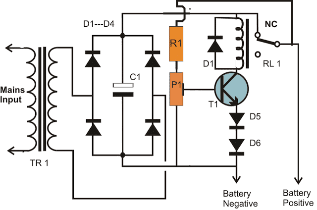
A simple arrangement with a single transistor linked in its typical working mode is seen in the diagram. The following information can be used to understand how the circuit functions:
We are aware that it is recommended to charge the battery until it attains between 13.9V and 14.3V since the battery that has to be charged is a 12 volt battery.
Employing the preset P1, one may modify the transistor base voltage so that at about 14 volts, the transistor just activates and turns ON the relay.
Setting up the Cut of Thresholds
When the battery hits 14 volts or is fully charged, this setting serves as the circuit's high voltage trip point, cutting off the battery's charging voltage.
Because this circuit is too basic and lacks a low voltage sensing feature, the lower cut-off point of the circuit can't be changed.
But in the event that its base voltage drops substantially, the transistor inherently functions as an ON/OFF switch.
A general-purpose transistor, such as the one depicted (BC547), generally has a lower voltage threshold of about 10 volts meaning that it may simply switch OFF when it is set to switch ON at 14 volts.
Due to significant design hysteresis, there is a significant voltage differential between the higher set threshold and the lower natural threshold. This causes a hysteresis in the design that is natural.
Since the battery voltage cannot be allowed to drop below this hazardous level of 10 volts, we are unable to stand by and wait for the circuit to resume the charging process.
The battery's life may be shortened and it may go irreversibly flat if it is allowed to deplete to 10 volts. Thus, the circuit needs to lower the hysteresis threshold in some way in order to resolve this problem. To do this, add a few diodes to the transistor's emitter.
As is well known, a 1N4007 diode would typically drop around 0.7 volts across it, and a pair of them would result in a total voltage of 1.4 volts. Both of the diodes are inserted in series with the transistor's emitter to compel the transistor to turn off at 1.4 V sooner than its typical indicated limit of 10 volts.
Consequently, the circuit's lower operational threshold is now 10 + 1.4 = 11.4 volts, which is deemed to be perfectly acceptable for the battery and the automated charging procedure restart.
Our automatic automobile battery charger is now affordable to construct and intelligent enough to manage battery charge conditions effectively, as both thresholds have been upgraded to align with conventional charging needs.
Circuit Diagram

Parts List for the proposed one transistor automatic battery charger circuit
R1 = 4K7 =1
P1 = 10 K preset =1
T1 = BC547B = 1
Relay = 12 V, 400 Ω, SPDT = 1
TR1 = 0 - 14V, current 1/10th of the battery Ah = 1
Bridge diodes = 1N5408 = 4
Emitter diodes = 1N4007 = 2
C1 = Electrolytic capacitor100 µF / 25 V = 1
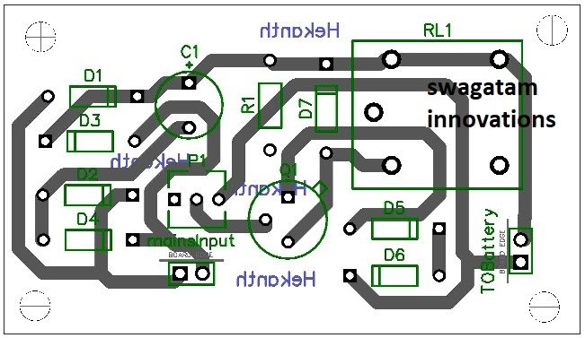
PCB Design