
With its parameters, the previously stated fence charger is comparatively bigger and more powerful. The following circuit for a tiny fence charger circuit might be quite helpful if you're looking for anything smaller.
Insects like cockroaches, slugs, worms, and snails may be kept at bay with this, whether it's used to protect food items or any other desirable tiny space like a terrace garden or porch pot vegetation.
How the Circuit Works
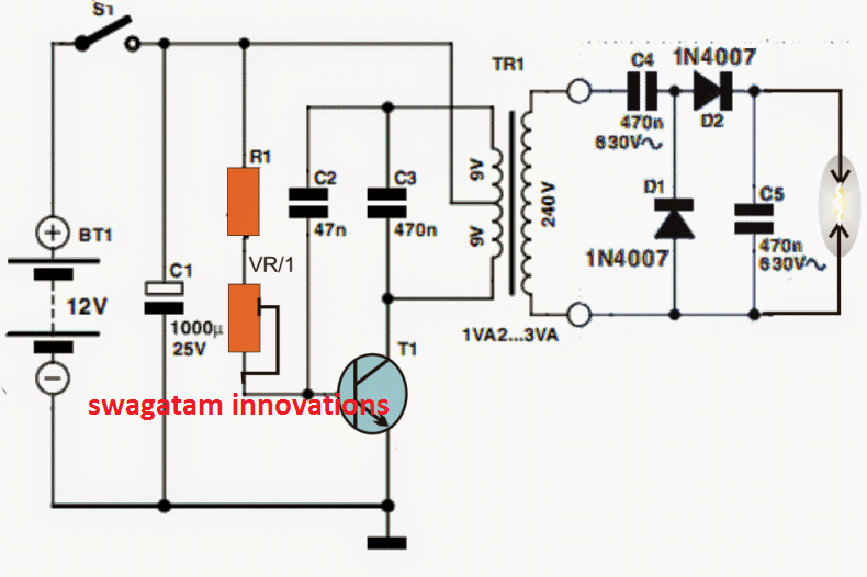
The tiny fence charger's referenced circuit is displayed below; the following information might help you understand it:
The transistor's base is essentially reinforced by the top portion of the transformer winding through C2. As a result, T1 remains in the conduction state until C2 fully charges, breaking the latch and forcing the transistor to start the conduction sequence over.
While VR1, which may be a 22k preset, may be adjusted to obtain an appropriately pulsing T1 rate, R1, which may be a 1K resistor, is inserted to limit the base gain for T1 to secure inhibits.
By experimenting with different values, C2 might be further fine-tuned before the optimum level of output is reached at the transformer output.
Which Transformer would Work Optimally
The transformer may be any of the 500mA iron-cored step down transformers that are frequently used in transformer-based AC/DC power supply units.
In the event that the secondary voltage is 220V, for example, the output that passes through the transformer could exist at the assessed secondary level, and this quantity could be predicted.
The coupled diode, capacitor charge pump configuration in accordance with the Cockroft-Walton power generation technology may allow for an even greater degree of elevation or step-up of the foregoing.
Through the use of a set-up that pushes the 220V output to thousands of volts, the charge pump circuit's end connections could be forced to spark up.
For the purpose of carrying out the planned fence charging activities, the aforementioned high voltage end terminals might be correctly linked up across the entire length of the area that has to be protected from insects.
The fence charger wires need to be at least a certain distance apart in order to prevent sparks from flying even in the case that insects do not penetrate the perimeter.
By replacing the iron core transformer with a ferrite core equivalent, the described small fence charger circuit design might also be used for mosquito swatter bat purposes.
Circuit Diagram

Very Simple Fence Charger Circuit using Two Step-Down Transformers
Without requiring any complicated circuitry, you might be able to utilize the following straightforward transformer-based AC fence energizer circuit provided you are able to connect to a 220V AC or 120V AC mains input.
The fence may be powered by the low current 220V side.
You may use a 0-6V / 220 V transformer for the right-side transformer to raise the output voltage to 500V AC.
You may also correctly raise the Ampere output of the two transformers in the event you want to improve the output's current strength.

In accordance with the amount of electric shock required for the application, the value of the capacitor can be determined.
Note: Even though this system uses transformers to decrease the input current to much lower levels, any living creature that gets trapped or ensnared in the fence and is exposed to the current for an extended period of time might be killed by the electrical output of the system, which can be sufficiently large. Construct this at your own risk, please.
Another Small Fence Charger Circuit using Transistors

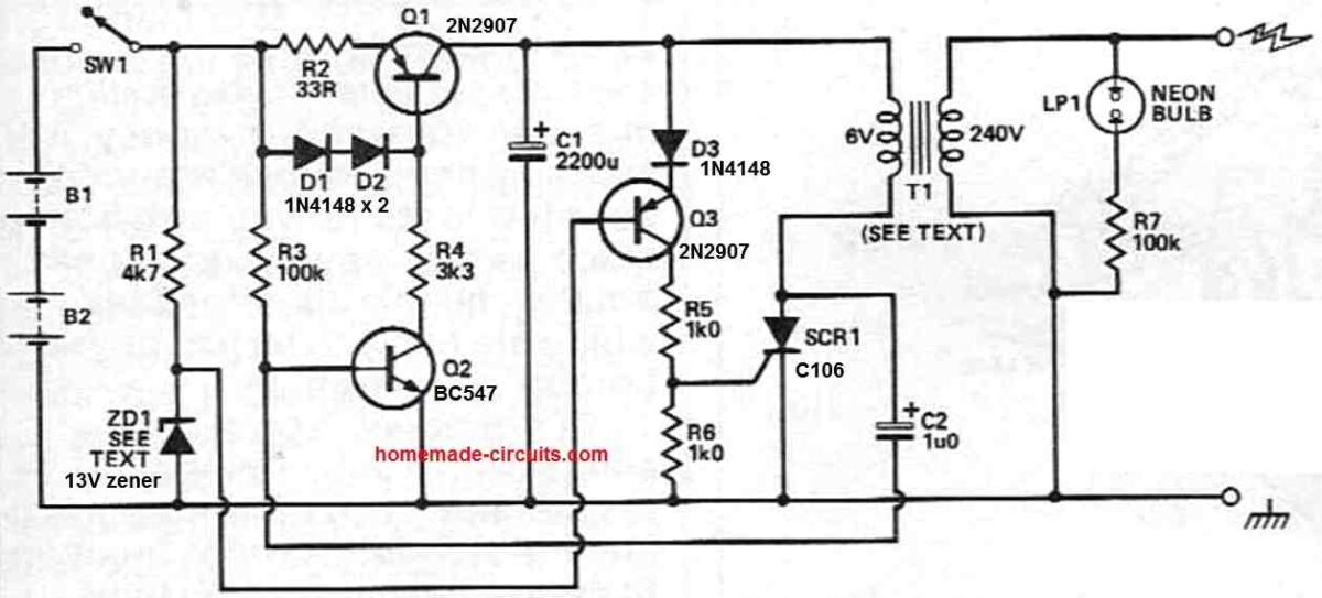
In this small fence charger circuit, transistor Q1 facilitates the constant current charging of capacitor C1.
Conduction via D3 is made possible when the capacitor's charge reaches about 14.3V thanks to the zener diode ZD1, which keeps Q3's base at 13V.
The gate trigger for SCR1 is delivered by the conduction in Q3. The modified 6V winding in the transformer's primary then experiences a discharge due to C1.
At the circuit's output, which is connected to the fence, this action produces a high-voltage pulse.
The gate drive to SCR1 is removed by the discharge of C1, enabling SCR1 to shut off as soon as the current drops to zero.
In order to protect against reverse breakdown, diode D3 stops too much current from passing through Q3's base-emitter junction.
The transistor is kept safe since the current is restricted to the reverse leakage current of the diode.
When there is an open circuit, SCR1 shuts off on its own and the transformer starts to ring a little bit. This causes Q1's current to go toward C1 rather than SCR1.
Once the circuit is loaded, this automated turn-off isn't guaranteed. In order to ensure that SCR1 turns off reliably, C2 and Q2 momentarily cut off Q1's current, giving SCR1 time to recuperate.
It is no longer necessary to touch the output terminals to verify the fence charger circuit's functionality visually thanks to a resistor and neon lamp combination.
Every time the fence charger pulses, the lamp flashes, signaling that it is working.
Any regular step-down transformer may be used as the T1 transformer; it only has to be coupled in backward to scale up the 6V input to 240V.