
Any solar panel may be used to maximize battery charging with this compact and accurate comparator-based solar battery charger configuration, which also guards against unintentional overloading.
With the longer battery life it provides, it's an expenditure that rapidly makes up for lost time.
Circuit Description
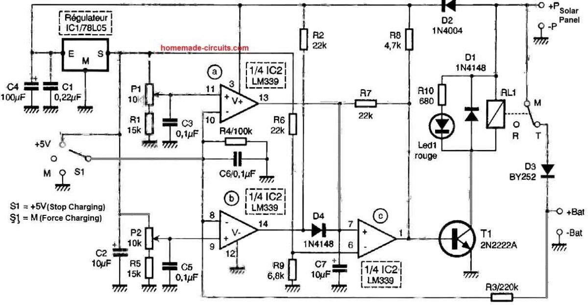
The only component in our setup is a dual comparator, which connects the panel to the battery when the voltage at the battery terminals falls under a particular value and disconnects the connection when it rises over that specific level.

It is especially useful for lead-acid batteries with liquid or gel electrolytes because they just need battery voltage monitoring to function. These batteries respond effectively to this method.
IC2a and IC2b are two comparators. The battery voltage is supplied to their inputs after it is split using R3 and R4.
The output of IC2b increases when it falls below the P2-set threshold, which likewise elevates the output of IC2c.
The solar panel can power the battery and replenish it via D3 since T1 is turned on and relay RL1 is turned on.
The output of IC1a drops low when the voltage at the battery terminals rises beyond the threshold established by P1.
This sets off the similar reaction in IC1c and de-energizes the relay, preventing any overcharging of the battery.
P1 and P2 are energized by the integrated regulator IC1, which is deliberately insulated from the voltage generated by the solar panel using D2 and C4 to guarantee that the limits they establish stay constant.
This is due to the fact that there are large fluctuations in voltage while relay switches, which may have an impact on how well the comparators function.
Additionally, a switch is included which offers manual configuration management by raising or lowering the voltage on the inputs of IC2a and IC2b.
When necessary, this permits the disconnection or, on the other hand, enforced battery charging. It is evident that this switch stays in the midway location for automated functioning.
Setting up the Presets
The setting up process is quick, though it calls for P1 and P2 adjustments, which are straightforward to make using a basic regulated power supply.
In order to accomplish this, provided DC supply to the configuration between -P and +P through a regulated power supply and keep the +BAT and +P points shorted.
Customize P1 and P2 while setting S to the midway location to ensure that the relay turns on at roughly 13V and turns itself off at approximately 14.5V from your power supply.
Everything should be enclosed in a weatherproof container to keep humidity away if the system is going to be used outside.
Additionally, keep it out of sunlight directly to prevent overheating that might change the P1 and P2 changeover thresholds.
Long-term consistent and dedicated performance of this comparator solar charger circuit may be guaranteed by adhering to the above two recommendations.