In this post we will discuss a few simple yet efficient solar voltage regulator circuits using the op amps like IC 741 and TL071.
Most common solar panels have an off-load voltage of about 19V.
This makes it possible to charge a 12V lead-acid battery and obtain a 0.6V drop across a rectifier diode. When it gets dark, the diode stops battery current from passing through the solar panel.

A 12V battery may easily be overcharged to above 15V if the charging source is not regulated, therefore this configuration works excellent for so long as the battery is not overcharged.
Typically, a series pass BJT induces a voltage drop of around 1.2V, which seems excessively high for almost all solar panels to function properly.
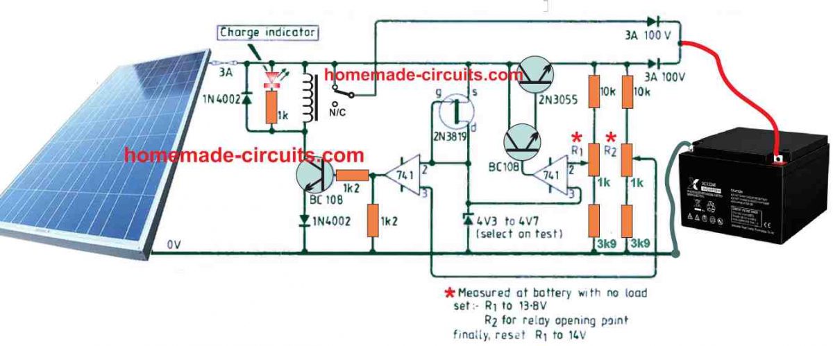
This straightforward solar regulator circuit efficiently eliminates both of the aforementioned problems. This is where a relay and rectifier diode are used to transfer power from the solar panel to the battery.
How the Circuit Works
The 2N3055 transistor starts to gradually charge the battery to an ideal 14.2V until the battery voltage reaches 13.8V, causing the relay contacts to operate.
Even though conventional lead-acid batteries begin to gas around 13.6V, this full charge voltage threshold might be set a little lower. The overcharge voltage causes a large rise in this gassing.
The instant the battery voltage falls below 13.8V, the relay contacts start to function. There is no need of battery power to run the circuit.
The FET functions as a steady-state current source.
Shunt Type Solar Voltage Regulator Circuit

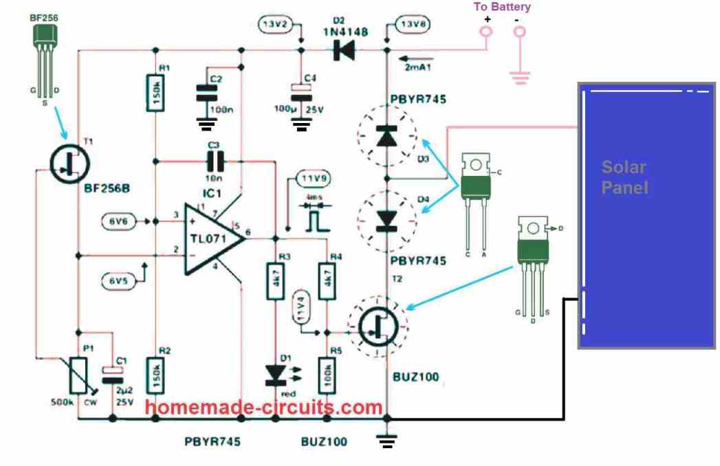
The following information may be used to understand the shunt type solar panel regulator circuit that is displayed above:
The TL071 op amp is set up similarly to a comparator.
For the op amp's inverting input, the FET BF256 and the 500k preset P1 combine to provide a constant voltage and current reference generator.
Pin 3, the non-inverting input for the op amp, functions similarly to the comparator op amp's over charge detection input since it is kept at a variable voltage source determined by the battery terminal voltage level.
From the moment as the battery achieves the full charge level, the preset P1 at pin2 of the IC is modified to ensure the expected voltage at pin3 input of the IC is little higher than pin2.
The voltage at pin 3 is smaller than pin 2 when the battery level is below the full charge value, maintaining the op amp's output at zero logic and turning off the FET T2 BUZ100.
The op amp's output switches to a high output immediately as the battery hits the full charge level, though, because the pin3 voltage now rises past the pin2 value.
This turns on the FET T1 right away, shunting the power from the solar panel to ground and stopping the battery from charging any more.
Since these two components ground the entire solar panel power, they can grow quite hot when the FET T1 shifts the voltage of the panel through the diode D4.
When the battery is charged, the diode D3 makes sure that it never discharges via the solar panel, especially at evening.
As soon as the battery is completely charged, the LED D1 turns on and off to signify this.
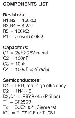
Parts List