
Be careful: Since these ELCB circuits haven't been put to the test in real life, extensive testing is necessary before putting them to use. Every circuit makes use of mains 2AC, and which if left uncovered and turned on might be dangerous.

ELCB Circuit Using a Triac
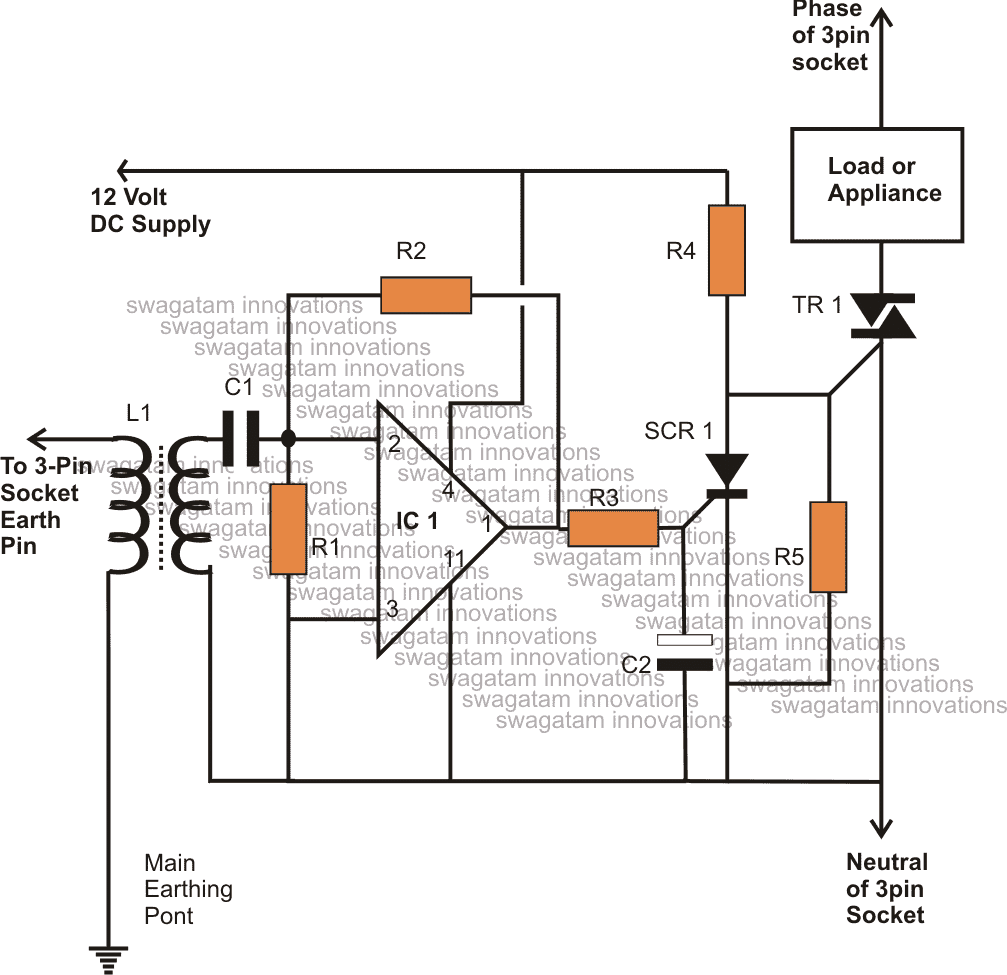
With the exception of the relay stage, that has been substituted with a triac, the circuit described above may also be built using a triac.
Under typical circumstances, the triac is permitted to conduct and manage the load while the IC output is kept off.
On the other hand, the SCR latches its anode to ground and the IC output rises high as soon as a leakage is detected.
This blocks the triac's gate current, causing it to abruptly stop conducting, turning off the load and correcting the adverse circumstances.

ELCB Circuit Using an SSR or Solid State Relay
Today, the mains AC controlled SSR devices are used to switch 220V operated loads more successfully over relays. Because they are solid state and electrically isolated, they are also becoming more popular than traditional switching devices like triacs and relays.
This is where the SSR gets the necessary input triggering voltage from the circuit, provided that everything else is normal.
But as soon as the circuit senses an impending earth leak, the SCR is activated, which blocks the SSR input signal to ground.
When the load trips, the SSR immediately ceases operating, carrying out the desired procedures and averting any potential danger.
Parts List
| Component | Specifications | Quantity |
|---|---|---|
| Resistors | ||
| R1 | 100K | 1 |
| R2 | 1M | 1 |
| R3, R4, R5 | 1K | 3 |
| Capacitors | ||
| C1 | 0.01uF | 1 |
| C2 | 100uF/25V | 1 |
| Inductor | ||
| L1 | Ordinary small output transformer as used in transistor radios | 1 |
| Semiconductor Devices | ||
| SCR | BT169 | 1 |
| Triac | BT 136 or higher current type | 1 |
| Operational Amplifier | ||
| Op amp | ¼ IC324 | 1 |
| Others | ||
| SSR | As per user specs | (Varies) |
| Relay | 12V, SPDT | 1 |