
Transistors can be connected in parallel when two or more of them have the same pinouts and specifications. This increases the combined power handling capacity of the transistors.
This article will teach you how to securely connect many transistors in parallel. We'll talk about both BJTs and MOSFETs.
Why Parallel Transistor may be Essential
Correct power output stage configuration becomes extremely important when creating power electronic circuits. This entails developing a power stage that requires the least amount of work to manage high power. Generally, a single transistor cannot accomplish this; instead, several transistors must be linked in parallel.
Power components like MOSFETs or BJTs may make up the majority of these stages. Generally speaking, one BJT is enough to provide a modest output current; however, if a greater output current is needed, additional of these devices must be added. As a result, connecting various devices in parallel becomes essential. While it is comparatively simpler to use single BJTs, connecting them in parallel requires careful consideration because of a notable characteristic flaw in transistors.
Understanding "Thermal Runaway" in BJTs
Transistors (BJTs) must be operated in suitably colder circumstances in accordance with their specifications in order to prevent their power dissipation from exceeding the maximum value that is prescribed. That's the reason we equip them with heatsinks in order to uphold the aforementioned standard.
Furthermore, BJTs' negative temperature coefficient forces them to raise their conduction rate proportionally in response to an increase in their case temperature.
The device begins to heat more rapidly when the current flowing across the transistor increases in conjunction with its body temperature.
This causes the BJT to heat up quickly, creating a chain reaction effect that damages it permanently when the device is too hot to handle. In transistors, this condition is known as thermal runaway.
Due to their marginally varying individual characteristics (hFE), two or more transistors linked in parallel can dissipate at varying rates—some a bit quicker and others somewhat slower.
As a result, the transistor—which might be carrying slightly higher current—might begin to heat up more quickly than the adjacent devices. Before long, the device might experience a thermal runaway, which could cause damage to it as it propagates the problem to adjacent devices.
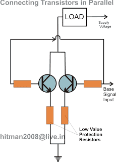
The problem may be resolved by connecting the emitters of each transistor in parallel and adding a low value resistor in series. The resistor prevents and regulates the current flowing through the transistors, ensuring that it never reaches hazardous levels.
The value needs to be determined correctly based on the amount of current that flows through them.
Connecting BJTs in parallel
The proper way to hook up two or more transistors in parallel is demonstrated in the circuit design that follows. In order to prevent a thermal runaway scenario, the emitter resistors ensure that the current distribution among the transistors is constant.

Solving Emitter Current Limiting Resistor in Parallel BJTs
In reality, it's pretty easy to compute with Ohm's Law:
V/I = R
where "I" may represent 70% of the transistor's maximal current handling capability and V is the supply voltage utilized in the circuit.
For instance, if you were to utilize the 2N3055 for the BJT, 70% of the device's maximum current handling capacity—roughly 15 amps—would be around 10.5 amp.
Consequently, if V = 12V, then
R = 12/10.5 = 1.14 Ohms
Solving Base Resistor
You may use the following formula to do this.
Rb = (12 - 0.7)hFE / Collector Current (Ic)
If we assume that hFE = 50 and load current = 3 amps, we may solve the above formula as follows:
Rb = 11.3 x 50 / 3 = 188 Ohms
Eliminating Emitter Resistors in Parallel BJTs
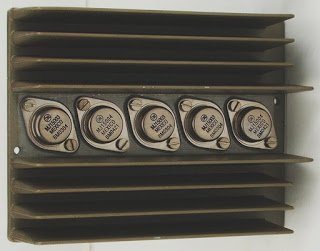
Even if using emitter current limiter resistors seems sensible and theoretically sound, mounting the BJTs atop a standard heatsink with a generous amount of cooling paste on their contact surfaces would be a simpler and wiser course of action.
You may eliminate the untidy wire-wound emitter resistors using this method.
By mounting above a shared heatsink, you may guarantee rapid and even heat distribution while averting the feared thermal runaway scenario.
Furthermore, since the transistors' collectors are meant to be linked in parallel, the need for mica isolators is eliminated, which simplifies matters considerably because the transistor bodies are connected in parallel via the metal of their heatsinks.
It's almost like a win-win scenario: the transistors readily combine in parallel via the heatsink metal, doing away with the large emitter resistors and preventing a thermal runaway.

How to Hook up MOSFETs in Parallel
We studied how to securely link BJTs in parallel in the paragraph above. However, the situation with mosfets is completely different and much more favorable to these devices.
Because mosfets do not have negative temperature coefficient issues, they are not susceptible to thermal runaway conditions brought on by overheating, in contrast to BJTs.
Conversely, these devices have positive temperature coefficient features, which means that as the temperature rises, the devices start to conduct less effectively and start to block current.
Consequently, there are no concerns when connecting mosfets in parallel, and you can proceed to connect them in this manner without requiring any current-limiting resistors, as demonstrated below. It is not really important, however it is worth considering to use independent gate resistors for every mosfet.

Conclusion
We thoroughly studied how to connect transistors in parallel in the discussion above. We may encapsulate the process as follows:
Whenever bipolar transistors are coupled in parallel, each transistor must have an appropriately sized emitter resistor added. This resistor eliminates the thermal runaway issue in BJTs by allowing the BJTs to distribute the load current and thermal dissipation uniformly.
To prevent a thermal runaway scenario and ensure consistent heat dissipation, you may wish to put the transistors tightly over a single common heatsink instead of using emitter resistors.
Since MOSFETs are negative coefficient transistors, they do not have the potential for a thermal runaway, so source resistors are not necessary.
Yet, to achieve good efficiency from parallel MOSFETs, they should be mounted atop a suitably rated heatsink.