
This low battery alarm circuit using IC 555 was initially used in conjunction with an automated mains/battery DC power supply to power transceivers.

Having the power supply usually at 13.6 V and the battery at 12 V, its function primarily is to identify a dip in DC voltage and to offer simultaneous visible and alarm notifications for such drops.
With the extra bonus of a sound warning, this low battery alarm using IC 555 is appropriate for a variety of applications that call for recognizing a reduction in voltage in the conventional DC power supply.
In cars, where a visual signal could be accidentally missed, this function is very helpful.
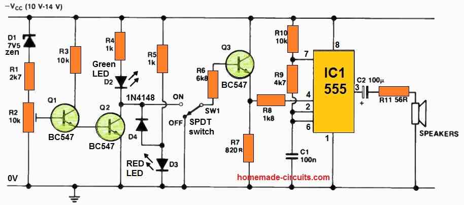
D1, R1, and R2 together provide the steady voltage referencing, and R2's setting is adjusted to guarantee that D2 stays illuminated in typical conditions. As a result, D4 continues to be forward-biased, maintaining D3's off state.
D3 is turned off whenever the input supply induces a decrease in voltage across Q2, and SW1 then activates Q3 as a result.
This change in voltage at pin 4 (reset) of the 555 timer makes it positive, allowing the astable oscillator that is built into the timer to operate properly. R9 could be used to change the oscillation's frequency.
By turning on SW1, which stops the current to Q3, one may disable the low battery audio alert feature. D3 will however keep on offering a visual cue.