
I have got this gadget called an automatic water level controller circuit. It’s pretty neat, it checks if the water in my tank is too low or too high and then turns the water pump on or off to keep the water level just right.
These circuits are great because they can turn the pump motor on or off to control the water level in the tank.
The way the controller works is by looking at how much water is in the tank and where the sensor points are dipped in the water.
One of my blogs regular readers, sent me a cool circuit he made. He’s always coming up with new electronic stuff and this time he shared his latest invention with me through an email.
A Simple Automatic Water Level Controller with BJTs Only
Heres the circuit I’ve attached for a really basic and affordable water level controller.
It’s just a simple part of a bigger product I sell that has a bunch of safety features like cutting off when there’s unsafe voltage, stopping if there’s no water to pump, and giving warnings with lights and alarms.
This design does a couple of things, it automatically controls the water level and also turns off if the voltage gets too high or too low. It’s not a groundbreaking invention, you can find loads of designs for overflow controllers in various websites and books.
But my circuit is made super simple using only transistors and resistors. It uses the same transistor to detect both the water level and if the voltage is too high.
I usually test my circuits for a few months, and this one seemed fine. However some customers have pointed out a few issues recently which I’ll get into at the end of this email.
How the Circuit Works
So, here’s how my water level controller using only BJTs and it works in simple terms:
When theres enough water in the overhead tank, it makes sure that the pump stays off. It does this by keeping a switch (T2) on, which keeps another switch (T3) off.
When the water drops below a certain point, T2 turns off, and T3 turns on. This makes the relay and the pump start working (though the diagram doesn’t show how the pump is connected).
The pump will only stop when the water touches point A because at that point, C doesn’t do anything since T3 is on.
The pump will turn back on when the water goes below points B and C again. Theres also a setting (VR2) that turns everything off if the voltage gets too high, like above 250V. And another setting (VR1) for when the voltage is too low, like below 170V.
If the voltage drops to 170V, a part called Z1 stops working, which makes T1 stay off, and that turns the relay off.
T2 is pretty important in this setup. You can even add a high voltage cut-off board that you can buy from the market to this circuit.
The parts in this circuit usually work great but I’ve noticed a couple of issues:
- Theres some buildup on the sensor wire because of a reaction in the water, so it needs cleaning every couple of months. I’ve mostly fixed this by using AC voltage on the sensor wire with an extra circuit, which I’ll send you later.
- The relays contact points get a bit worn out because of sparks when the pump starts, which can make the pump heat up, especially if it’s an older one. To stop this from happening, you can use an extra motor starter. That way, the relay only has to manage the motor starter, and the pump won’t overheat.

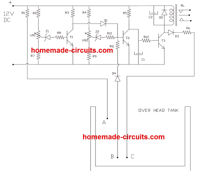
- PARTS LIST
- R1,R11 = 100K
- R2,R4,R7,R9,= 1.2K
- R3 -10KR5 = 4.7K
- R6 = 47K
- R8,R10 = 10E
- R12 = 100E
- C1 = 4.7uF/16V
- C2 = 220uF/25 V
- D1,D2,D3,D4 = 1N 4007
- T1,T2 = BC 547
- T3 = BC 639( try 187 )
- Z1,Z2 = Zener 6.3 V,VR1,
- VR2 = 10K PRESET
- RL = Relay 12V 200E, > 5 AMP CONT ( According to pump HP)