
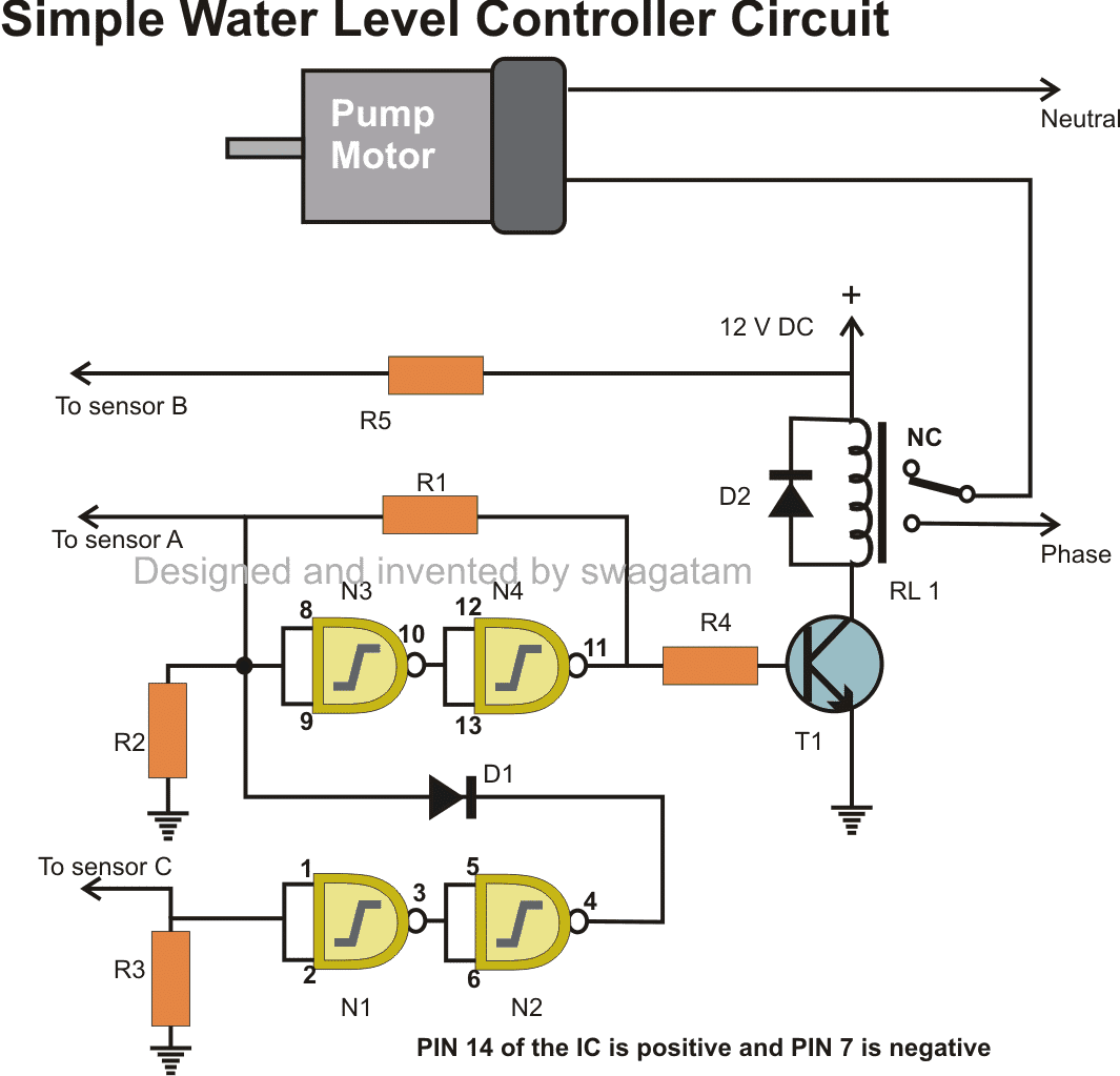
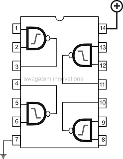
In the discussed circuit, a logic IC 4093 is utilized. Commonly, the water we receive in our homes, which isnt pure, offers little resistance to electricity.
To put it plainly, water can conduct electricity, though the effect is very slight. Typically the resistance of household tap water falls between 100 K and 200 K ohms.
This level of resistance is sufficient for electronics and is harnessed in the project outlined in this article, specifically for a straightforward water level control circuit.
For the necessary detection, four NAND Gates are employed.
The entire process can be grasped through the following points:


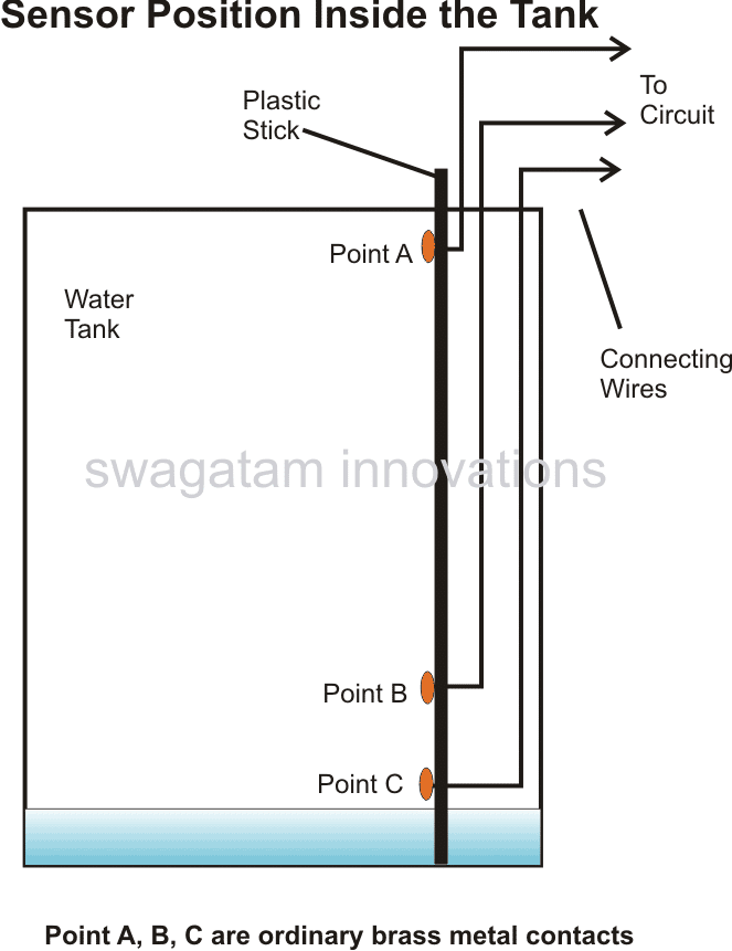
How to Place the Sensors
Looking at the diagram, the point B is at a higher electrical level and is located towards the lower part of the tank.
Point C is right at the bottom and point A is attached to the very top.
If the water level stays below point B then both points A and C will have a neutral or zero electrical level.
This also keeps the inputs of certain NAND gates at a low electrical state due to the 2M2 resistors connected to them.

How the Sensors Work
The NAND gate switches N2 and N4 are initially off so the relay and motor are off too.
Imagine the tank starts to fill up and when the water hits point B, it makes a connection with point C.
This turns on switch N1, which then turns on switch N2. But, theres a diode D1 in the circuit, so even though N2 is on, it doesn’t change anything earlier in the circuit.
When the water level hits point A, switch N3 turns on, and so does switch N4. NAND N3 and N4 stay on because of a feedback resistor connecting the output of N4 back to the input of N3.
With N4 on, the relay turns on and the pump begins to drain the tank. Even if the water drops below point A, N3 and N4 stay on because they’ are locked on, and the motor keeps running.
But, when the water level falls below point B, point C and the input of NAND N1 turn off, which turns off NAND N2.
At this point, the diode D1 becomes active and pulls the input of N3 down, which turns off NAND gate N4. This finally turns off the relay and the motor stops.
Parts List
- R1 = 100K,
- R2, R3 = 2M2,
- R4, R5= 1K,
- T1 = BC547,
- D1, D2 = 1N4148,
- RELAY = 12V, 400 OHMS,
- SPDT Switch
- N1, N2, N3, N4 = 4093